




news
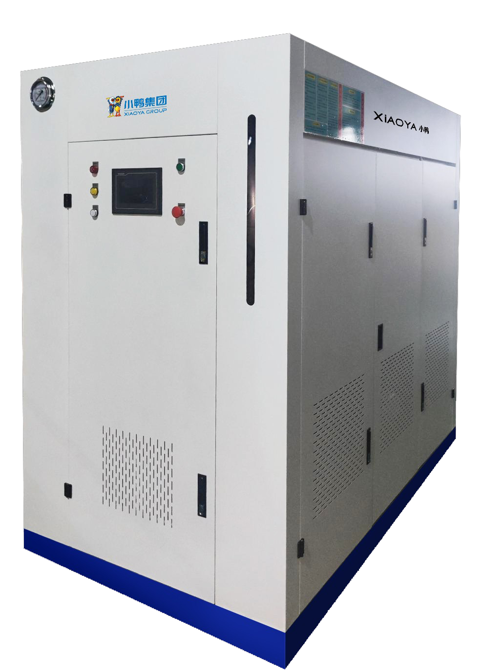
An HOCl generator machine can be ready for delivery while its installation site is still weeks away from being ready for operation. A water connection, an electrical outlet, and an available corner do not establish site readiness. The practical test is whether those services can support the selected machine through production, cleaning, shutdown, and maintenance without creating an unresolved discharge or ventilation problem.
For project managers, the first step is to obtain the model’s installation requirements and turn them into an agreed utility layout before equipment arrives. Confirm the required product chemistry at the same time: equipment described as an HOCl generator may differ from a sodium hypochlorite generator in output characteristics and supporting services. That distinction can affect water treatment, chemical handling, ventilation, and acceptance testing.
Water: check the supply under operating conditions
Start with a representative analysis of the water that will actually feed the machine. Hardness, conductivity, and other constituents can affect electrolysis, electrode deposits, and product consistency. The equipment supplier should identify acceptable feed-water limits and the treatment needed to meet them. A building’s existing drinking-water supply does not automatically satisfy the generator’s process requirements.
Water treatment also creates installation requirements of its own. A softener needs room for servicing and salt replenishment, with an appropriate route for regeneration discharge. Filtration requires access for replacement elements. If reverse osmosis is specified, account for its feed demand, reject-water discharge, and any storage or pumping equipment. These items belong in the utility scope and floor plan from the beginning.
Check pressure and flow at the proposed connection while other significant water users are operating. A static pressure reading can conceal a supply that drops below the machine’s requirements during peak building demand. Conversely, excessive pressure may require regulation. Establish whether the generator needs a direct supply, a break tank, or a booster arrangement, and assign responsibility for supplying those components.
Size the connection around the complete operating cycle. Depending on the design, water may be used for brine preparation, production, rinsing, and cleaning. An average daily consumption figure is insufficient for sizing a branch line if the machine draws water intermittently at a higher rate.
Before releasing the plumbing work, settle these connection details:
- The feed-water limits and any required pretreatment.
- The pressure and flow available at the machine during expected building demand.
- The connection size, isolation valve, and backflow protection required by the design and local rules.
- The location of sampling points and access for servicing treatment equipment.
Keep the product route separate from the feed-water assessment. If generated solution will enter a storage tank or dosing system, review the wetted materials, delivery distance, transfer method, and protection against backflow. A suitable water inlet cannot compensate for an incompatible product tank or an incorrectly connected dosing line.
Power: include the equipment around the generator
Use the selected model’s electrical schedule to confirm voltage, frequency, phase, connected load, and protective-device requirements. Do not infer these from the machine’s physical size or a sales description. A compact enclosure can contain an electrolysis power supply, pumps, controls, and auxiliary equipment with different electrical needs.
The site load assessment should include everything needed to keep the process running: pretreatment pumps, ventilation equipment, transfer pumps, tank controls, and any specified cooling equipment. Establish whether these loads receive power through the generator or require separate circuits. This prevents auxiliary services from being omitted when the main machine connection is priced and installed.
Ask how the system behaves after a power interruption. Automatic restart may depend on water availability, tank level, circulation, or ventilation status. Where continuous disinfection is essential, assess the required product reserve and the facility’s backup arrangements. Backup power alone does not establish continuity if another necessary service remains unavailable.
Place the electrical isolator where maintenance personnel can reach it safely, and keep electrical equipment clear of credible leaks, splashes, and cleaning activities. The electrician should verify earthing, circuit protection, cable routing, and enclosure suitability for the location. Required electrical working clearances must also appear on the layout.
For an automated installation, document the signals exchanged with the building or process control system. Low water supply, production faults, tank level, and ventilation status may need alarms or operating interlocks. Agree on what each signal does before commissioning; an alarm visible on the machine may be insufficient if the unit normally operates unattended.
Drainage: define what leaves the machine and where it goes
Identify each liquid discharge separately. Depending on the system, these may include pretreatment waste, rinse water, cleaning solution, off-specification product, tank overflow, and liquid released during maintenance. Their composition and discharge pattern can differ, so they should not be treated as one generic drain connection.
Confirm which streams may enter the available drainage system under local requirements and the site’s wastewater arrangements. Some may need collection or treatment before disposal. Where cleaning chemicals are used, review their compatibility with residual disinfectant and other connected waste streams. Acid contacting hypochlorite can release chlorine gas, making shared collection points and cleaning procedures a significant design consideration.
A nearby floor drain does not prove that the proposed drainage arrangement will work. Check its capacity, destination, connection height, and susceptibility to backup. Where gravity drainage is specified, maintain the required fall and avoid routing that retains liquid. Provide an air gap or other separation where required to prevent wastewater returning to the equipment.
Overflow arrangements deserve particular attention when production feeds a storage tank. Establish how a high-level condition stops production and how an overflow would be contained. A drain should not serve as the routine means of controlling tank level. Leak detection or secondary containment may also be appropriate, depending on stored volume and the consequences of a release.
Record the drain destination on the installation drawing. This gives the installer, commissioning team, and facility operator a common reference and reduces the chance that a temporary hose connection becomes the permanent arrangement.
Space: allow for servicing, consumables, and gas handling
The required installation area extends beyond the generator’s footprint. Allow room to open doors, withdraw electrodes or filters, service pumps, access valves, and move replacement components. Check the delivery route as well: door openings, corners, floor loading, and lifting access can constrain installation before the machine reaches its final position.
Reserve space for salt or other specified consumables, water treatment, product storage, and transfer equipment. Position replenishment points so operators can use them without reaching across electrical equipment or obstructing maintenance access. If the unit is installed in a washdown area, verify its environmental rating and protect surrounding components accordingly.
Gas handling must follow the selected electrolysis design. For example, the Sodium Hypochlorite Electrolyzer uses membrane-free electrolysis of a dilute sodium chloride solution to produce sodium hypochlorite, with hydrogen as a byproduct. Its push-type hydrogen removal design uses high-flow circulating solution to help carry hydrogen away from the compact composite electrode surface. The installation still needs a defined means of separating and safely discharging that gas; removal from the electrode does not establish safe disposal from the room.
This example also illustrates why output chemistry should be settled before installation. Sodium hypochlorite solution contains chlorine species whose balance depends on conditions such as pH. A generator’s name alone does not establish that its product meets an application’s required HOCl characteristics. Specify the required output pH and available chlorine concentration, then confirm that the selected process can deliver them.
Obtain the manufacturer’s ventilation, gas-discharge, ambient-temperature, and humidity requirements. Where hydrogen is produced, the vent route, discharge location, ignition-source control, and any required hazardous-area assessment should be resolved by qualified designers. Do not assume general room ventilation can replace a specified gas-handling arrangement.
Before delivery, have the plumbing, electrical, controls, and installation leads walk through the approved layout together. Verify the installed services against the requirements, including access and discharge routes. Commissioning can then demonstrate output quality, production rate, alarm response, shutdown behavior, and safe operation through a complete cycle. Handover should leave the facility team with recorded acceptance results, operating procedures, and clear maintenance responsibilities.
NEWS
 Hypochlorous Acid Gains Recognition in Chinese Farm Emissions Guidance
- Disinfection Empowers Orthodontic Safety: Hypochlorous Acid Generators Build a Sterile Defense Line for Dental Instruments
- Accumulating Strength and Reaching New Heights: A Record of the Production Breakthrough of Xiaoya Small Home Appliances' Hypochlorous Acid Generators
 Installing an HOCl Generator Machine: Water, Power, Drainage, and Space
 HOCl Generator Machine Specifications: Rated Output vs. Usable Capacity


Leave us a message

Xiaoya Group was founded in 1979,expert in the electrolyzed water industry.
Get in Touch
*We respect your confidentiality and all information are protected.