




news
Low free chlorine from a hypochlorous generator calls for two early measurements: a fresh sample at the generator outlet and a sample at the point where the solution is used. If both are low, investigate measurement accuracy and generation conditions. If the outlet meets specification but the downstream sample does not, investigate dilution, storage, or chlorine consumption before replacing the electrolytic cell.
Record the operating mode, free chlorine, pH, feedwater temperature, salt preparation, actual flow, and displayed current during the same production run. Compare these readings with the manufacturer’s limits for that configuration. Measurements collected under different settings can create a misleading fault pattern.
Confirm that the low reading is real
Use a free chlorine test suited to the expected concentration. Free chlorine and total chlorine are different measurements; a total chlorine result cannot substitute for the required free chlorine value. With a DPD method, use the correct reagent, observe the specified reaction time, and confirm that the instrument’s measurement range covers the sample.
A very high chlorine concentration can produce a falsely low or colorless DPD result through reagent bleaching. If the result is unexpectedly close to zero, repeat the measurement using the test method’s approved dilution procedure and chlorine-demand-free dilution water. Apply the dilution factor. Uncontrolled dilution with tap water introduces uncertainty because the water can contain chlorine or substances that consume it.
Collect the sample in a clean, compatible container and test promptly. Detergent residue, contamination, sunlight, and delays between collection and measurement can change the result. Flush stagnant liquid from the sampling point first, then sample after the generator has reached its specified stable operating condition.
Where an online sensor reports low chlorine but a suitable independent test gives a normal result, inspect the sensor’s sample flow, fouling, calibration, and compensation settings. ORP alone cannot establish free chlorine concentration: its response also changes with pH and other substances in the water.
Use the outlet-to-use-point difference to locate the fault
Sample directly after generation, before a storage tank or dilution connection, wherever the equipment provides an approved sampling point. Compare that result with the tank outlet or dispensing point, allowing for the time required for fresh solution to travel through the system.
A downstream loss does not establish poor cell performance. Organic residues and other reactive contaminants consume free chlorine, while heat, light exposure, and extended storage accelerate deterioration. A tank containing leftover rinse water also lowers concentration through dilution. These causes require different corrective actions.
Resolve feed chemistry before adjusting electrical settings
Verify the specified salt type, preparation method, and dosing ratio. Undissolved salt, an empty brine reservoir, restricted suction tubing, or a dosing pump that moves less liquid than its setting indicates can reduce chloride delivery. Inspect the complete feed path; a normal reservoir level does not prove that brine reaches the cell.
Conductivity helps assess feed consistency, but it does not identify chloride concentration by itself. Other dissolved ions also raise conductivity. A change in source water or an unsuitable salt grade can therefore produce an apparently acceptable conductivity reading while the feed differs from the approved formulation. Compare measurements using the specified temperature compensation and sampling location.
Do not keep adding salt to chase a low chlorine result. Excess salt can move the unit outside its operating limits, affect current and temperature, and leave the original fault unresolved. Restore the documented recipe first.
Measure product pH alongside free chlorine. pH determines the balance between hypochlorous acid and hypochlorite ion, which affects disinfection behavior. A shift toward hypochlorite does not, by itself, prove that total free chlorine has fallen; a suitable free chlorine method measures both forms. An abnormal pH instead provides evidence to investigate feed composition, any specified acid dosing, or mixing conditions.
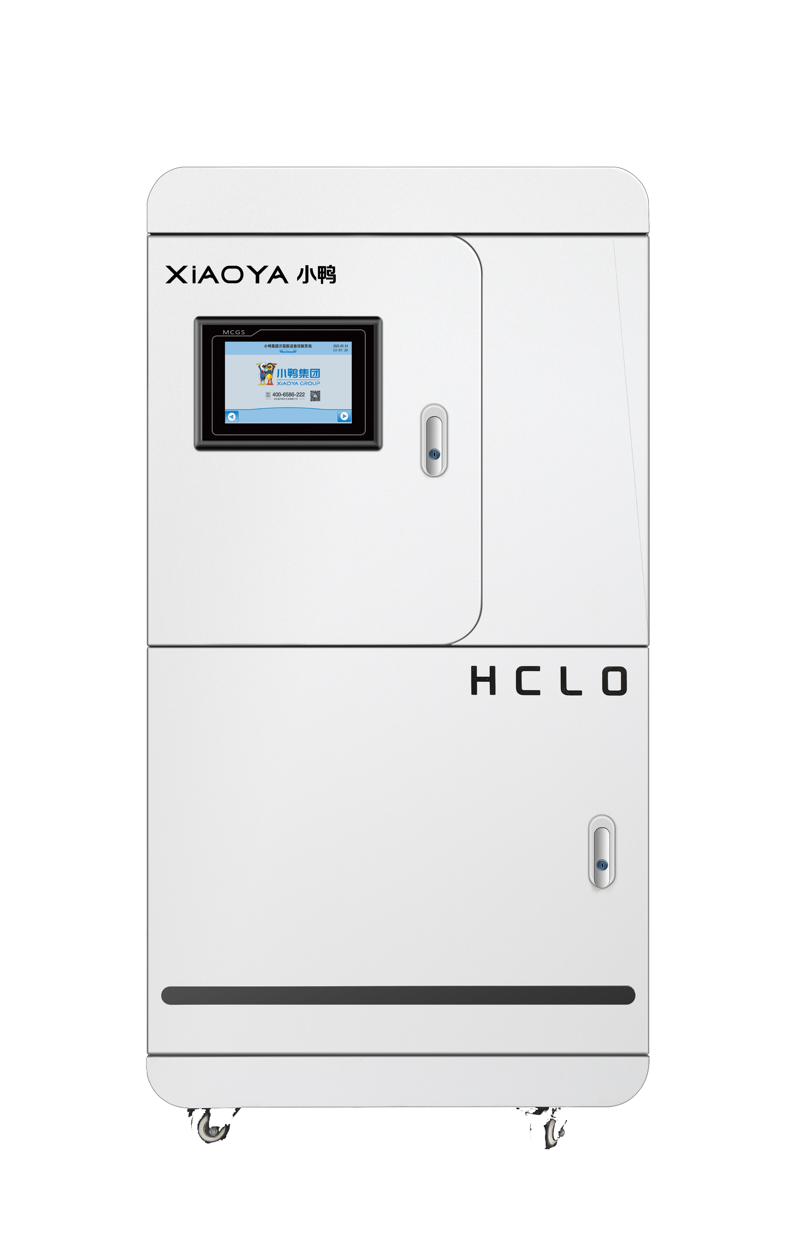
For a model such as the Hypochlorous Acid Generator for Public Health (AQ-P1000), use its own operating documentation to establish the acceptable recipe, output, and service procedures. Settings from a different generator are unsuitable as diagnostic targets unless their equivalence is documented.
Read current, voltage, and flow together
Chlorine production is related to electrical charge passing through the cell, while outlet concentration also depends on how much water carries that production. For a continuous-flow generator operating at similar efficiency, increasing flow without increasing chlorine production lowers outlet concentration. For a batch unit, fill volume and electrolysis duration determine the comparable relationship.
Measure actual flow using the approved method instead of relying solely on a pump setting or flow display. A replacement pump, changed inlet pressure, incorrect valve position, or miscalibrated flow sensor can alter throughput. In a batch system, confirm the fill level and whether the cycle completes rather than stopping early.
Interpret electrical readings according to the power supply’s control mode. In a current-controlled system, rising voltage at the same current suggests increased electrical resistance. Once the supply reaches its voltage limit, current can fall. In a voltage-controlled system, increased resistance directly reduces current. Low conductivity, scale, poor connections, and cell deterioration can produce overlapping symptoms.
Compare the commanded output with the actual current during production. A lit display does not establish that the cell receives stable power. Intermittent current drops warrant investigation of supply faults, thermal protection, connectors, and interlocks. Electrical measurements inside the enclosure require the equipment’s prescribed service procedure.
Inspect the cell when the operating evidence points there
Hardness deposits on electrodes or within flow passages can restrict water movement and increase resistance. Suspect scaling when performance deteriorates progressively, electrical readings change from the established baseline, and the feedwater or maintenance history supports deposit formation.
Before opening the cell or disconnecting plumbing, isolate electrical power and follow the specified depressurization and draining procedure. Inspect accessible passages, seals, and electrode surfaces without scraping or abrading coated electrodes. Mechanical damage to the coating can turn a recoverable maintenance issue into permanent loss of performance.
Use only the manufacturer-approved cleaning agent, concentration, contact time, and rinsing procedure. Acid cleaning must remain separate from chlorine-containing solution because contact can release chlorine gas. Drain and rinse as directed before introducing any approved cleaner.
After cleaning, repeat measurements under the same feed and flow conditions used before service. Recovery of current and chlorine output supports scaling as the cause. If performance remains low with correct feed chemistry, verified power, and clear passages, investigate electrode wear, internal leakage, or separator damage where that design uses a separator.
Demonstrate recovery under the original operating conditions
Change one variable at a time and record the resulting current, voltage, flow, pH, and free chlorine. Simultaneous changes to salt dosing, flow, and electrical settings obscure which correction worked and complicate any repeat failure.
Complete verification at both the generator outlet and the point of use after the system stabilizes. For an intermittent fault, observe the relevant production cycle, refill event, or warm operating period. Retain the verified settings and readings as the service baseline; they provide a concrete comparison if chlorine output falls again.
NEWS
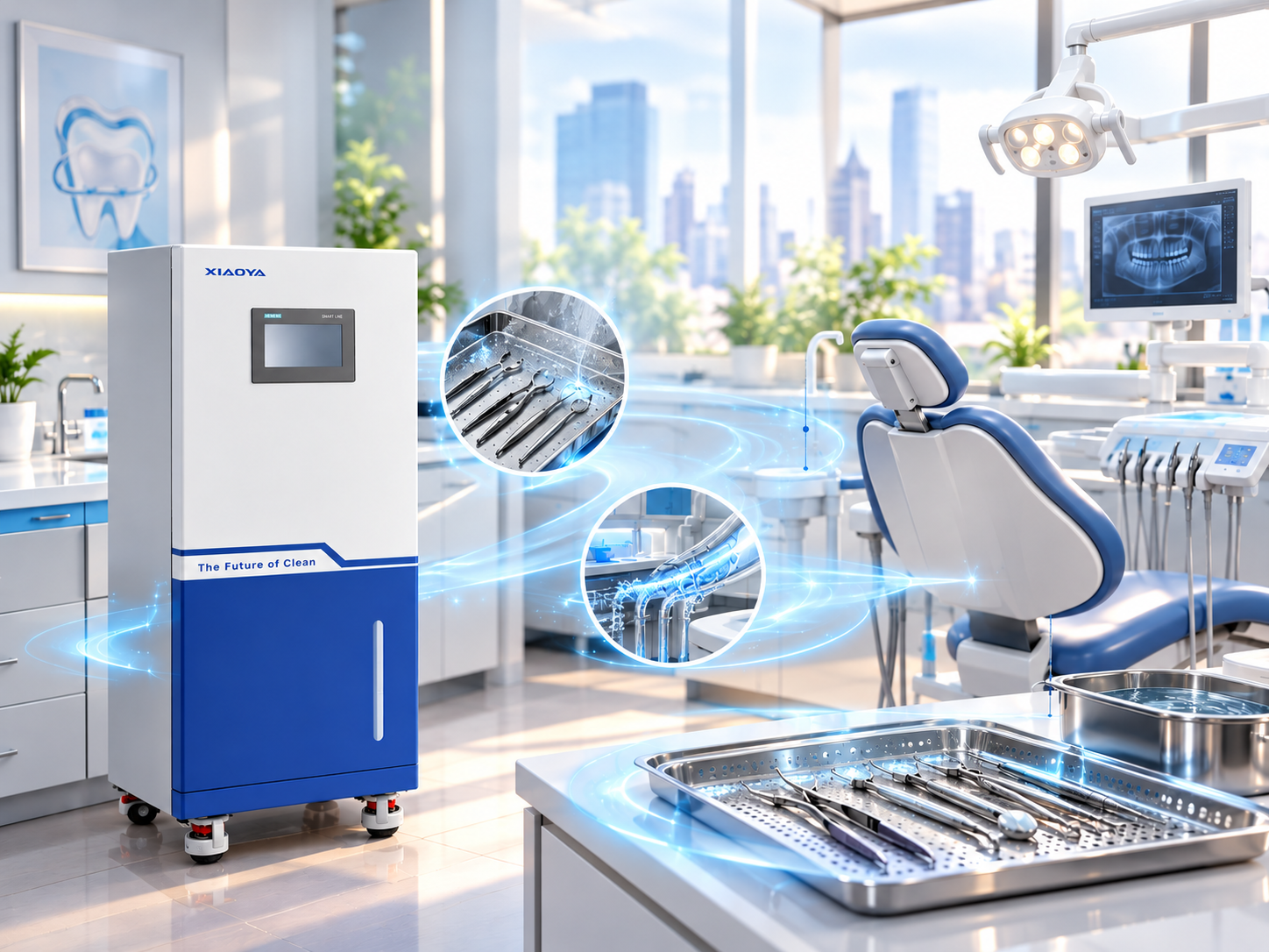
 Disinfection Empowers Orthodontic Safety: Hypochlorous Acid Generators Build a Sterile Defense Line for Dental Instruments
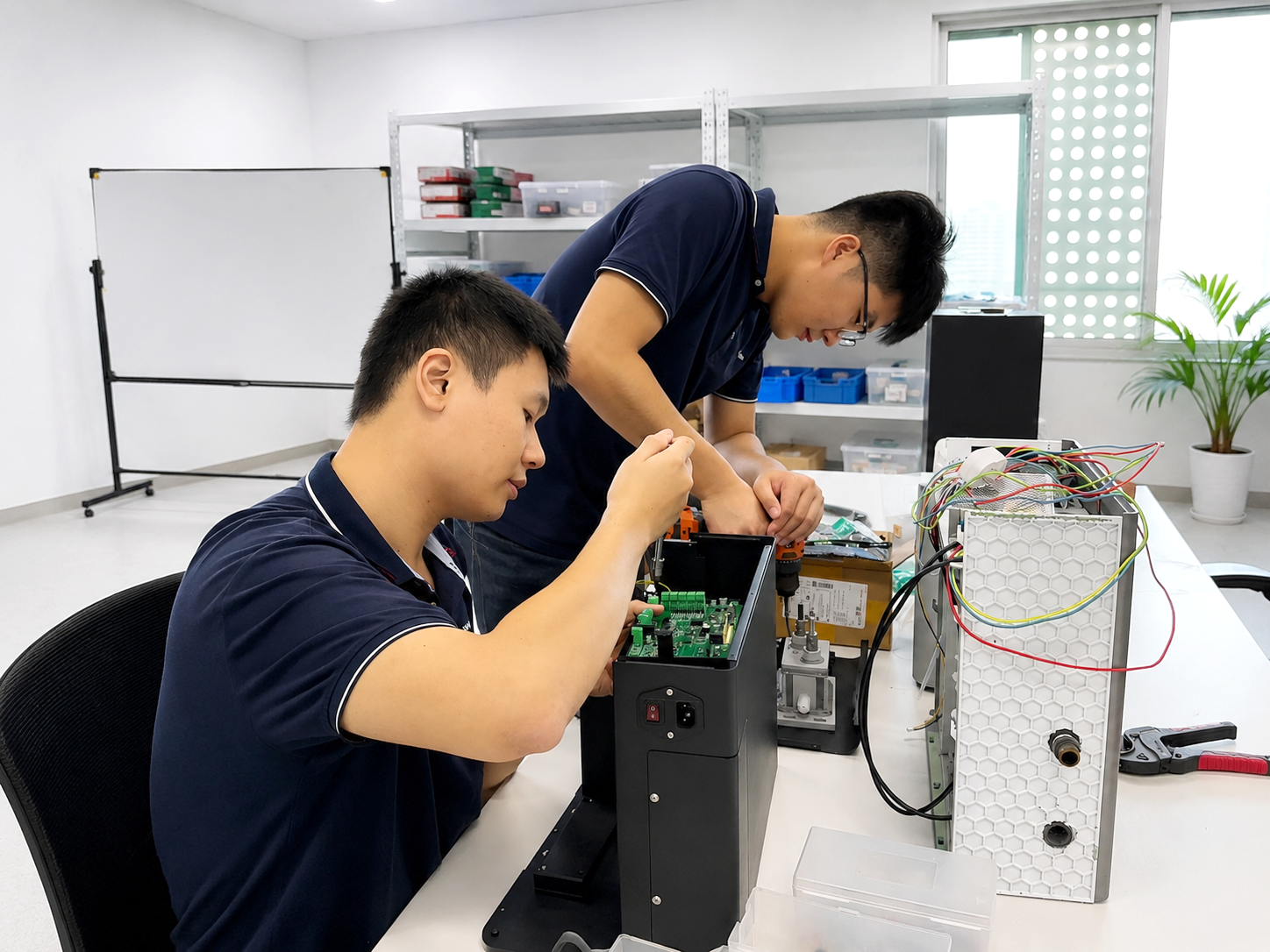
- Accumulating Strength and Reaching New Heights: A Record of the Production Breakthrough of Xiaoya Small Home Appliances' Hypochlorous Acid Generators
 Why Is Your Hypochlorous Generator Producing Low Free Chlorine?
 Hard Water and Hypochlorous Generators: When Is Pretreatment Needed?
 Hypochlorous Generator Chemistry: Why pH Changes HOCl Availability


Leave us a message

Xiaoya Group was founded in 1979,expert in the electrolyzed water industry.
Get in Touch
*We respect your confidentiality and all information are protected.